System Sensor 2151a Wiring Diagram

B114lpbt Plug In Detector Base Manualzz
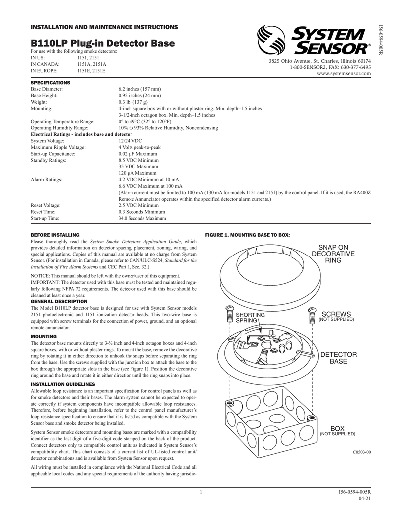
B110lp Plug In Detector Base Manualzz
The System Sensor 2151 Cut Sheet Manualzz

System Sensor B112lp Installation Manual Alarm Grid
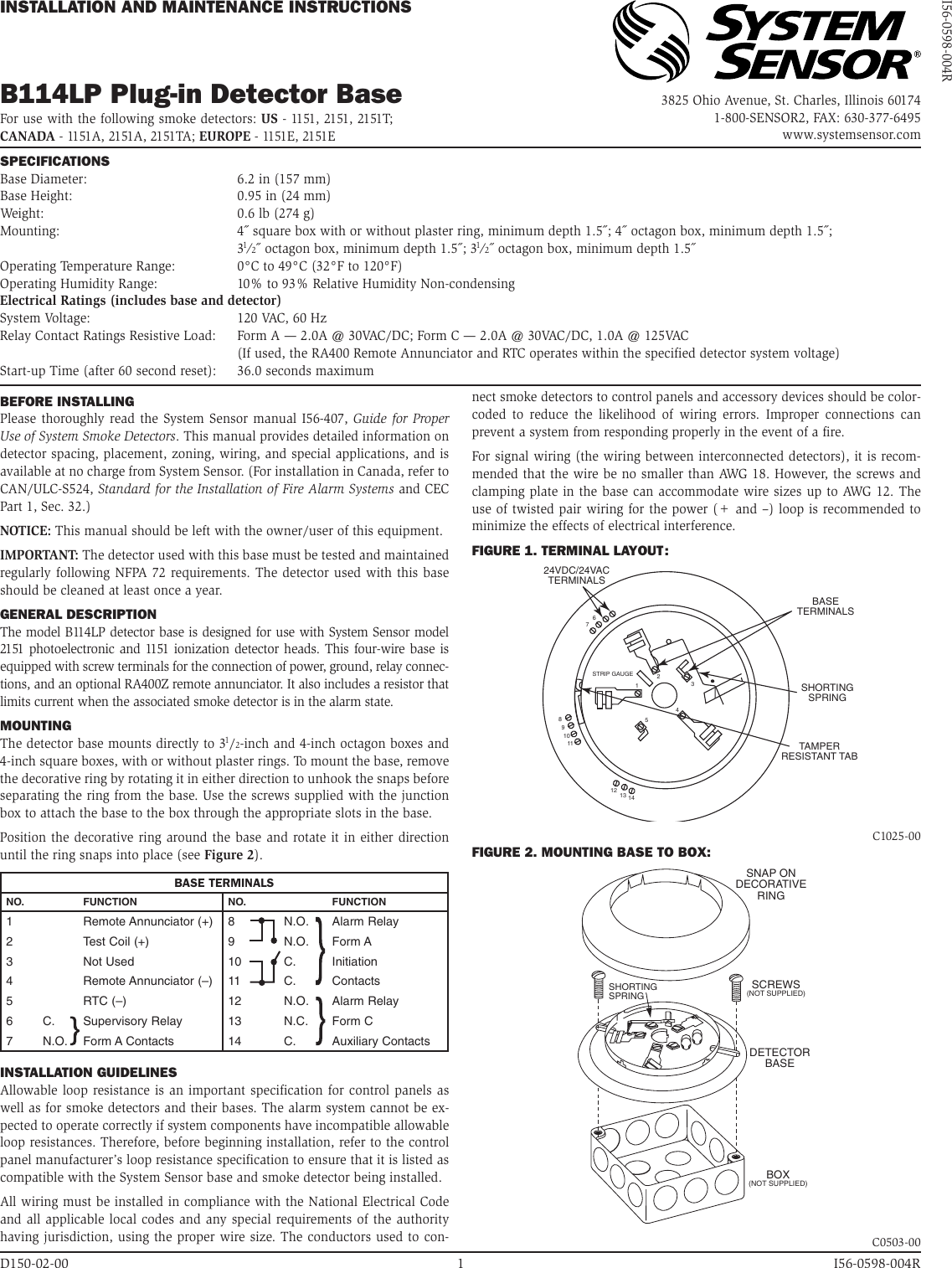
System Sensor B114lp Users Manual

Hardwired Smoke Detectors System Sensor Alarm Wiring Smoke Detector Emergency Lighting Smoke Detectors

The non polarized screw terminals on the back of the detector will accept 14 22 awg wire.
System sensor 2151a wiring diagram. 2151 products system sensor system sensor. For best system performance all wiring should be installed in separate grounded conduit. System sensor manufactures smoke and heat detection duct and sprinkler monitoring and emergency notification products. The use of twisted pair wiring for the power and loop is recommended to minimize the effects of electrical interfer ence.
905 812 0771 www systemsensor ca before installing please thoroughly read twothe system sensor manual i56 407 guide for proper use of system smoke detectors. Please thoroughly read the system sensor manual i56 407 guide for proper use of system smoke detectors which provides detailed information on detector spacing placement zoning wiring and special applications. We design fire carbon monoxide and heat detection and notification devices that use the most innovative technologies in the most inventive ways. However the screws and clamping plate in the base can accommodate wire sizes up to awg 12.
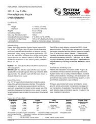
Copies of this manual are available from system sensor. 2151a low profile photoelectronic plug in smoke detector installation and maintenance instructions 6581 kitimat rd unit 6 mississauga ontario l5n 3t5 1 800 sensor2 fax. Innovation is our way of life. Wiring for signal wiring the wiring between interconnected detectors it is recommended that the wire be no smaller than awg 18.
The air duct smoke detector shall be a system sensor model 2151 series smoke detector listed to ul 268a specifically for use in air handling systems when used in conjunction with the b114lp or b114lpbt base. This manual should be left with the owner user of this equipment. Can prevent a system from responding properly in the event of a fire. System sensor is a global manufacturer of fire and life safety devices in smoke detection carbon monoxide detection and notification technology.
Cop ies of this manual are available at no charge from system sensor. Please also refer to can ulc s524 standard for. Our products are convenient to install efficient to operate and offer the highest level of.

2 Wire Photoelectric Duct Smoke Detector System Sensor Canada

800 Series Low Profile Plug In Smoke Heat Detectors

New Wiring Diagram Ruud Ac Unit Thermostat Wiring Diagram Heat Unit

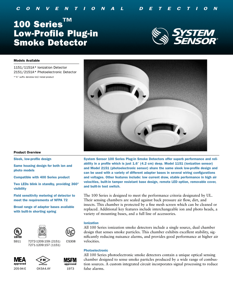
System Sensor 100 Series Low Profile Plug In Smoke Detectors International Safety

Fire Alarm Wiring Diagram Fire Alarm Smoke Alarms Alarm


Types Of Fire Alarm Systems And Their Wiring Diagrams Fire Alarm System Fire Alarm Alarm System

Hardwired Smoke Detector Wiring Diagram With Nm B 14 3 Cable Smoke Alarms Hardwired Smoke Detectors

Dsp 0501 Wiring Diagram Cnc Machine Tools Wire Control System
Https Www Pottersignal Com Product Harrington Hs 3030 Installationmanual Pdf

Unique Wiring Diagram For Goodman Gas Furnace Diagram Diagramsample Diagramtemplate Wiringdiagram Diagramchart Thermostat Wiring Goodman Furnace Diagram

Es200 Wiring Diagram Connection Scheme Diagram Automatic Sliding Doors Wire

